Categories
Embedded Engineering Linux Python

Red Pitaya using only pyVISA

The Red Pitaya boards offer an SCPI server over an TCP/IP Socket connection. The makers describe how to use it. But instead of using plain pyVISA, they provide their own SCPI class.

That’s fine, because that class also provides handy functions to set the various in-built applications (signal generator and the likes).

But it is unnecessary complicated for a blinky example. And in my case, where I only needed some scriptable DIOs, it was quite cumbersome.

So, here is the blinky re-written in plain pyVISA:

import pyvisa as visa
from time import sleep

rm = visa.ResourceManager()
rp = rm.open_resource("TCPIP::169.254.XXX.XXX::5000::SOCKET",
                 read_termination="\r\n",
                 write_termination="\r\n"
                 )

print(rp.query("*IDN?"))

while True:
    rp.write("DIG:PIN LED0,1")
    sleep(.5)
    rp.write("DIG:PIN LED0,0")
    sleep(.5)

The magic lies in the read and write terminations. They have to be set to '\r\n'(in that order), or else the communication simply won’t work and time out.

Make sure you install a reasonably recent pyVISA and pyVISA-py (from pip) or libvisa (from your distro’s repository) before you start. For me (Ubuntu) this works as follows:

pip install -U pyvisa pyvisa-py
sudo apt install libvisa

This integrates nicely with existing instrument command structures and allows for quick testing.

Categories
Arduino Embedded Hardware

Arduino* and a custom board

At work a colleague developed a custom board in the time of chip shortage™ and had to use a 20 MHz oscillator in place of a 16 MHz requiring a custom board configuration. The solution after searching the often misleading Arduino forums was to hack it into the global platform.txt.

This is neither portable nor does it interact well with updates of the Core. Fortunately, there are very good, not misleading forum posts!

A (hopefully more than just slightly) better solution is to use the hardware/ directory in the Sketchbook folder and to reference the standard Arduino configurations (using the VENDOR_ID:VARIANT_ID notation).

  • Let’s name the board gsino since my colleague and I work at GSI.
  • Then let’s create a folder structure $SKETCHBOOK/hardware/gsi/avr and …
  • … write a basic boards.txt shown below:
gsino.name=GSino Board

gsino.upload.tool=arduino:avrdude
gsino.upload.protocol=arduino:arduino
gsino.upload.maximum_size=32256
gsino.upload.maximum_data_size=2048
gsino.upload.speed=144000

gsino.bootloader.tool=arduino:avrdude

gsino.build.mcu=atmega328p
gsino.build.f_cpu=20000000L
gsino.build.board=AVR_UNO
gsino.build.core=arduino:arduino
gsino.build.variant=arduino:standard

If the created folder contains only this board.txt file, the menu entry in the IDE for this board will be “Tools/Board/gsi-avr/GSino Board”. If you want it a little prettier, create a platform.txt with

gsino.name=GSino
gsino.version=1.0.0

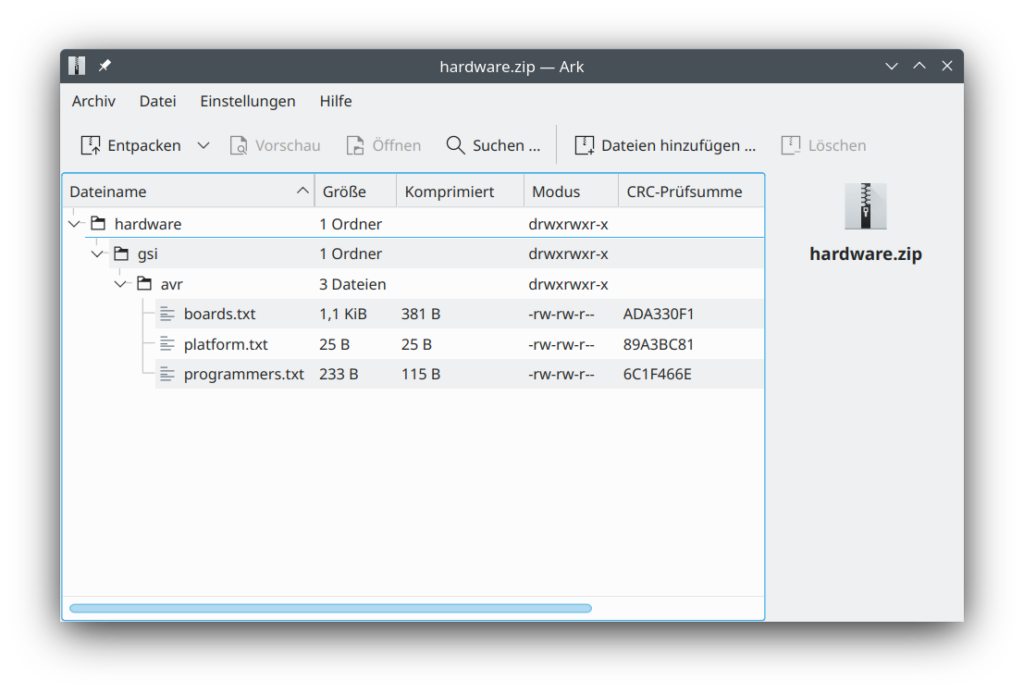
Voilà! If you need to take this to another computer or share it with a friend, just zip the relevant parts of the $SKETCHBOOK/hardware/ folder and unpack it in its new location.

Screenshot of the archive showing the folder hierarchy: "hardware/gsi/avr/" with the three relevant files "boards.txt", "platform.txt" and "programmers.txt".

And there you have a slightly more portable and cleaner solution to writing your own hardware platform.

*) This was done on Arduino IDE version 1.8.19 and should work for quite a while (probably after version 1.5.x). AFAIK, this should work similarly with the new 2.0 IDE. But I did not test this.